Posts

Assignment 3 - Reflection

Image
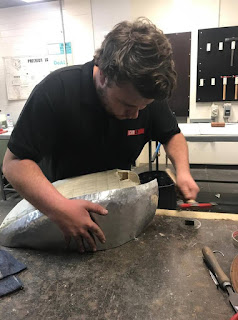
Assignment 3 - Reflection - Fuel Tank Throughout the semester, undertaking the digital making course, the overall goal of the individual sessions and tutorials was to guide us students through each of the submissions that were required but ultimately was to provide skills, tips and techniques that will help us deliver the final assignment the “Fuel Tank”. This reflection will critically review the process behind and finished product. The goal of the fuel tank assignment was to join into groups to deliver a successful 1:1 scale template that replicated one of the designs that were provided and create an aluminium skin that reflected and adhered to the shape and contours of the fuel tank itself. Difficulties: To deliver the fuel tank successfully a specific procedure and process needed to be utilised to ensure that; we created a template that was 1:1 scale and it replicated the shape as much as possible. These procedures required the utilisation of specific tools and programmes

Assignment 2 - Fuel Tank

Image
Assignment 2 - Fuel Tank: Assignment Requirements: As part of a team, we were required to create a 1:1 scaled template that replicated a motorcycle fuel tank. The fuel tanks were supplied by the course lecturers / tutors. As an individual we needed to create an aluminium mould that replicated the look of one third of the fuel tank  Techniques Utilised During Assessment: Shrinking and Expanding of the Aluminium Curvatures Crimping of Aluminium  Process: 1. Take photos of Supplied Fuel Tanks To allow the group to create the 3d model, a range of photos at different angles where taken to ensure that the software could recognise the shape and mould of the fuel tank itself. The photos that were taken needed to depict the curvature and the size to ensure that the shaping process could be completed as smoothly as possible.  2. Create 3d Model The next process involved utilising the software - Rhino to reconstruct the 3d model. To allow the model to be created usin

Beil 0014 - The Torus

Image
The Torus: Creation Process: 1. The first step of the torus was to measure and cut the aluminium sheet to correct size. The next step was to create some guide-lines that were able to ensure that the correct shape was achieved.  2. By utilizing the timber stumps that were provided, clamped into the vice the general curvature was created through hitting the middle / divot in the stump to get the first curve along the centre of the metal.  3. The next stage involved utilsing the anvil to create the other method of curvature. By moving the aluminium into different directions / angles the overall curvature to the external of the aluminium was developed whilst maintaining the curvature created by the stump.  4. Then by using a plenishing hammer, the overall marks / lumps in the torus could be removed however required more finishing methods at a later stage. Another benefit that the plenishing hammer had was the fact that it was able to refine the overall external curvatu

Beil0014 - The Tray

Image
The Tray: Process: 1. The first step of the process to create the aluminium tray is to cut the aluminium sheet using the shears and timber filler pieces to the desired size, incorporating the correct width and fat allowance on the side to ensure that the metal was not left short on either side. 2. By utilizing the stencils provided, the correct and accurate diameters was achieved and was easily conveyed onto the aluminium to ensure that the best finish was achieved. 3. After the correct size and diameter was achieved, the forming process begun. Focusing on folding the edges by utilising the square head mallet (as shown below) and ensuring that no folds / creases were evident. This was achieved by slow and cautious hits focusing on one side of the corner then cutting the excess material where evident. 4. After all edges and sides were bent to ensure a correct 90 degree angle was achieved, a light sand was desirable. By using the sanding board (shown below

Beil 0014 - Blister

Image
The Blister: Creation Process: 1. The first step the create the blister involved choosing a desirable formed CNC template that was provided by the built environment workshop. This template was going to be utilized to form the blisters overall shape, depth and look hence it was critical to choose the correct shape. The shape i chose was an overall much slimmer shape which would be critical to utilize the correct tools and techniques that had been learnt in the previous weeks to ensure that look of the blister was maximised. 2. From this, the next process was to ensure the aluminium sheet provided was the correct shape and size and did not slide out of the mdf material by using nuts and bolts to tighten to the correct force.  3. The next process was to create the wooden tool that would be used get the overall shape of the blister sharper and get into the corners where the sphered mallet would not. Throughout the overall process of the blister, the wooden tool was chang